


Views: 0 Author: Site Editor Publish Time: 2026-07-21 Origin: Site


Co-locating wind and solar generation creates complex power dynamics across modern grids. The compounding complexity of these combined resources requires precise voltage regulation. They also demand robust bidirectional power flow management to maintain grid stability. Standard distribution transformers consistently fail in these harsh environments. They cannot withstand the specific harmonic loads generated by Battery Energy Storage Systems (BESS). Frequent switching events and intense thermal stresses quickly degrade standard insulation materials. Premature equipment failures lead to catastrophic downtime and severe financial losses. Project engineers and EPC contractors must carefully evaluate specialized components. We will explore how to specify and procure containerized BESS transformers correctly. You will learn actionable strategies to ensure long-term grid stability. These insights help guarantee project bankability without facing massive cost overruns. Proper component selection remains the ultimate safeguard for hybrid renewable facilities.
Properly sizing a BESS transformer requires analyzing site-specific duty cycles and harmonic profiles, not just peak megawatt ratings.
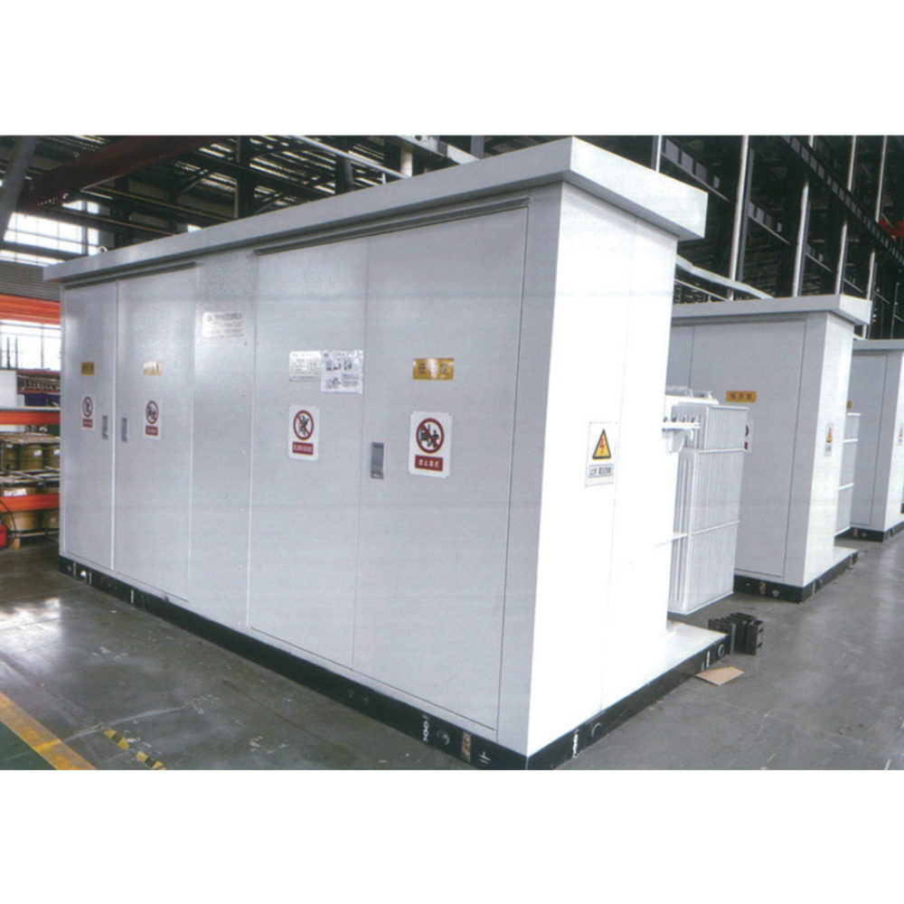
Integrating energy storage container transformer systems reduces onsite civil works, compresses commissioning timelines, and ensures controlled internal thermal environments.
Grid compliance relies heavily on performance modeling (e.g., NERC guidelines) and verifiable fault ride-through capabilities.
Vendor selection must weigh upfront CAPEX against long-term operational costs, focusing on warranty terms, Factory Acceptance Testing (FAT), and lead-time reliability.
Hybrid power plants introduce unique operating realities for grid infrastructure. They combine volatile generation sources with massive battery reserves. Operators rely on the bidirectional nature of BESS units daily. They store excess midday solar power. They also capture overnight wind energy. Operators then discharge this stored power during peak demand hours. This constant cycling creates highly variable load profiles. Transformers must handle rapid power reversals without experiencing magnetic core saturation. You must account for these daily operational swings during the initial design phase.
Voltage step-up requirements form the next major integration hurdle. Inverter output voltages typically sit at very low levels. They usually range between 400V and 1500V. The plant must elevate these voltages to match medium-voltage (MV) or high-voltage (HV) collection grids. Precise impedance matching becomes critical here. If the step-up process lacks efficiency, energy losses multiply rapidly. System designers must specify transformers capable of stepping up power cleanly. This ensures maximum revenue generation from the hybrid plant.
Project developers now prioritize footprint and modularity goals heavily. Traditional substations require extensive onsite civil works. They demand concrete foundations, specialized enclosures, and lengthy assembly times. You can bypass these hurdles by deploying pre-integrated, skid-mounted solutions. Fully integrated Energy Storage Container Transformer Systems offer a compelling business case. They minimize expensive on-site labor. They also mitigate weather-related installation delays. Factory integration guarantees better quality control than field assembly. This modular approach accelerates project timelines significantly.
Thermal management dictates the lifespan of any energy storage infrastructure. Traditional base-load transformer sizing fails miserably for BESS applications. Standard sizing assumes steady, predictable loads. BESS operations create aggressive, spiky thermal loads. Rapid charging and discharging generate immense heat. If engineers ignore these dynamic temperature rises, the transformer will overheat. You must evaluate the thermal time constant of the windings. This ensures the unit can handle sudden bursts of full-rated power.
The choice between liquid-filled and dry-type transformers requires careful analysis. Liquid-filled units offer superior cooling capacities. However, they introduce fluid containment requirements. Dry-type units eliminate spill risks entirely. They often fit better into strict fire safety zones. We must also factor in environmental impacts. Solar radiation heavily impacts containerized systems. Ambient temperatures increase the internal HVAC load assumptions. Your thermal modeling must include external heat gain on the steel container.
Table: Cooling Medium Comparison
| Cooling Feature | Liquid-Filled Transformers | Dry-Type Transformers |
|---|---|---|
| Heat Dissipation | Excellent thermal capacity for heavy loads | Moderate capacity, relies on forced air |
| Fire Risk | Requires high fire-point fluids (e.g., ester) | Inherently self-extinguishing materials |
| Maintenance | Requires periodic fluid sampling and testing | Minimal upkeep, mostly visual inspections |
| Footprint | Often larger due to radiator fins and tanks | Highly compact, ideal for tight containers |
Harmonic mitigation requires precise engineering. BESS inverters generate significant non-linear loads. These loads produce severe harmonic distortion. High-frequency harmonics cause excessive eddy current losses. This heat degrades insulation prematurely. You must specify an appropriate K-Factor for the transformer. The K-Factor rating indicates the unit's ability to handle harmonic heating. Standard distribution units lack this specialized winding design. Failing to manage harmonics leads to inevitable core failures.
Duty cycle resilience separates standard units from BESS-rated components. Energy storage systems transition rapidly between active and idle states. A plant might charge at full capacity, drop to zero, and discharge heavily minutes later. These frequent transitions cause mechanical stress. The transformer windings experience constant expansion and contraction. Robust winding designs prevent mechanical deformation. You should demand specialized clamping structures to secure the coils against these dynamic forces.
Grid compliance remains a strict barrier to entry for hybrid plants. System specifications must map directly against recognized industry guidelines. You must adhere to IEEE and IEC standards for transformer manufacturing. Furthermore, NERC reliability guidelines govern BESS hybrid performance modeling. Grid operators require detailed proof of system stability. They will reject interconnection applications lacking comprehensive modeling data. You must treat these standards as mandatory design inputs.
Interconnection requirements demand verifiable fault ride-through capabilities. Grid faults cause sudden voltage drops or spikes. The plant must not disconnect immediately during these events. Transformers must support low-voltage ride-through (LVRT) protocols. They must also handle high-voltage ride-through (HVRT) scenarios. These capabilities help stabilize the broader grid during temporary disturbances. Selecting robust Energy Storage Container Transformer Systems Solutions ensures compliance with these critical interconnection rules.
Data transparency from equipment vendors is absolutely vital. You cannot perform accurate pre-construction modeling without real data. Vendors must provide exact positive and zero sequence impedance values. They must supply verified loss curves from similar units. Engineers feed this data into power flow and short-circuit models. If a vendor hides this information, your simulation results will fail. Transparent data prevents costly redesigns late in the project lifecycle.
Chart: Harmonic Mitigation Parameter Summary
| Parameter | Standard Definition | BESS Requirement |
|---|---|---|
| THD Limit | Under 5% typically | Often exceeds 15% during heavy switching |
| K-Factor | K-1 (Linear load) | K-4 to K-13 depending on inverter type |
| Shielding | Basic electrostatic | Advanced Faraday shields between windings |
Navigating transportation logistics presents significant challenges for containerized systems. Heavy containerized transformers require specialized hauling equipment. Weight constraints often dictate the maximum size of a single shipment. You must evaluate site access limitations early. Rural wind and solar farms often feature unpaved or narrow access roads. Heavy cranes require stable ground for offloading. Ignoring these logistical realities causes severe schedule delays. Engineers must factor transportation limits into the overall modularity strategy.
Environmental protection and fluid containment demand rigorous planning. Liquid-filled transformers pose potential soil contamination risks. You must evaluate built-in fluid spill containment solutions. Many modern containers feature integrated catch basins. Corrosion resistance is equally important. Coastal or offshore wind proximities expose equipment to salt fog. You must specify C4 or C5 marine-grade paint requirements. This specialized coating prevents rapid container degradation in harsh environments.
Vendors frequently advertise "plug-and-play" commissioning features. You must assess the reality behind these pre-commissioned claims. Factory integration certainly reduces site work. However, no system is entirely plug-and-play. You still have mandatory site-specific testing obligations. Grounding systems require local validation. You must complete protection relay coordination based on the final grid connection. Never assume the container can simply be turned on without localized safety checks.
Consider this standard workflow for post-placement commissioning:
Visual and Mechanical Inspection: Check the container for transit damage. Ensure all internal mounting bolts remain torqued to specification.
Insulation Resistance Testing: Megger test all windings to confirm moisture did not compromise insulation during transit.
Relay Coordination and Injection Testing: Verify the protection relays communicate correctly with the site's main SCADA system.
HVAC and Auxiliary Power Checks: Power up the cooling systems to confirm proper airflow and ambient temperature management.
Energization and Soak Period: Energize the transformer without load. Monitor it for 24 hours to check for abnormal vibrations or thermal hotspots.
Evaluating upfront CAPEX alone leads to poor financial decisions. You must factor in long-term lifecycle efficiency. Initial purchase prices tell only a fraction of the story. No-load losses consume power constantly, even when the BESS is idle. Cooling energy consumption also impacts overall plant revenue. Inefficient HVAC systems drain significant auxiliary power. You must calculate the expected maintenance intervals over a 20-year lifespan. High-efficiency units cost more initially but yield substantially better project returns.
Vendor capabilities dictate supply chain security. You should evaluate supplier track records meticulously. Ask for specific case studies involving wind-solar hybrid plants. Assess their sourcing redundancy for critical components. Copper windings, specialized bushings, and relay controllers often face global shortages. A reliable vendor maintains multiple supply avenues. They provide realistic lead times and stick to them. Late transformer deliveries will delay entire hybrid plant energizations.
Developing a strict shortlisting logic protects the project timeline. Follow specific criteria to filter out unqualified suppliers quickly. Always require documented proof of passing routine and type tests. Do not accept theoretical performance claims. Evaluate the availability of their aftermarket support. Regional service teams matter when unexpected faults occur. Without local support, minor issues cause weeks of downtime.
Test Documentation: Demand recent type test certificates for identical thermal and harmonic ratings.
Service Footprint: Ensure the vendor has certified technicians within a 24-hour travel radius.
Design Flexibility: Verify they can customize container dimensions to fit tight site layouts.
Warranty Terms: Look for comprehensive guarantees covering both the transformer and auxiliary cooling systems.
Next Step Action: Request detailed FAT protocols and thermal modeling reports from shortlisted vendors. Submit these documents for independent engineering review before signing purchase agreements.
Selecting the right containerized transformer system is a foundational engineering task. It bridges the critical gap between volatile hybrid generation and stable grid export. Hybrid plants demand components capable of extreme thermal and harmonic resilience. Repurposed standard distribution transformers will fail under these unique conditions. They jeopardize both grid reliability and investor returns.
We strongly recommend prioritizing solutions validated by transparent factory testing. Ensure your specified equipment is designed exclusively for energy storage duty cycles. Protect your asset by demanding rigorous K-Factor ratings and advanced cooling mechanisms.
Engage with technical engineering teams early in the Front-End Engineering Design (FEED) stage. Align your transformer specifications tightly with plant interconnection agreements. Taking proactive steps today ensures a profitable, stable, and compliant renewable energy facility tomorrow.
A: Standard units are designed for steady, predictable loads. BESS applications introduce severe harmonic load profiles and bidirectional power flows. The intense, rapid cycling between charging and discharging creates massive thermal stress. Standard insulation and cooling systems cannot dissipate this localized heat. This causes them to overheat and fail prematurely in hybrid environments.
A: Containerization protects equipment from dust, moisture, and salt. However, it traps heat generated by inverters and transformers inside a confined space. You must balance this environmental protection with specialized HVAC or forced-air systems. Proper thermal modeling ensures internal cooling mechanisms can manage extreme heat loads without draining excessive auxiliary power.
A: You must supply accurate, dynamic plant data. Critical inputs include continuous power ratings, inverter switching frequencies, and the expected harmonic spectrum. You also need maximum ambient temperature data, solar radiation estimates, and the intended daily charge/discharge profiles to calculate thermal time constants accurately.
A: Grid operators demand strict stability proof before granting interconnection. Operators must provide highly accurate dynamic models of hybrid plants. Selecting a transformer with well-documented, tested impedance values and performance data is mandatory. Without this transparent vendor data, your plant will fail compliance modeling and face grid rejection.


