


Views: 0 Author: Site Editor Publish Time: 2026-09-17 Origin: Site


Power grids operate at massive, hazardous voltage levels to move electricity across vast distances. Your facility machinery simply cannot handle this raw power directly. An electrical transformer acts as the critical bridge between these utility power lines and your functional facility operations. Without precise voltage management, sensitive industrial equipment fails instantly. Energy goes to waste, and safety risks compound rapidly across your entire distribution network.
Every commercial building, manufacturing plant, and data center relies on these systems to operate safely. We wrote this guide to explain core transformer capabilities and operational mechanics. You will gain a clear framework for evaluating, specifying, and sourcing the right unit. This knowledge helps you select reliable, code-compliant solutions for demanding commercial or industrial applications.
To understand modern power distribution, you must first ask, what is an electrical transformer? At its most basic level, it is a static electrical device designed to transfer energy from one alternating current (AC) circuit to another. It performs this transfer while either increasing or decreasing the voltage. These units sit at the heart of every commercial power distribution system, acting as the gatekeepers between the raw utility grid and your internal electrical infrastructure.
Let us look at the transformer working principle in practical terms. The device relies entirely on electromagnetic induction. Inside the heavy steel enclosure, you will find two separate sets of wire coils wrapped around a highly conductive magnetic steel core. We call these the primary winding and the secondary winding. When alternating current flows into the primary coil, it creates a fluctuating magnetic field in the core. This invisible magnetic flux sweeps across the secondary coil. The sweeping motion induces a corresponding voltage in that secondary circuit. Because these units contain no moving mechanical parts, they remain incredibly reliable over decades of continuous use. However, the induction process inevitably generates heat. You must manage this thermal output carefully to prevent insulation degradation.
This simple physical process solves a massive business problem. Utilities generate and transmit electricity at extremely high voltages because it drastically reduces energy loss over long distances. High voltage transmission is cost-effective for power companies. However, this high voltage would instantly destroy standard facility machinery, commercial lighting, and HVAC systems. Transformers bridge this gap. They safely step down the high transmission voltage to the specific, lower voltage your equipment requires. Additionally, they provide crucial electrical isolation. Because the primary and secondary coils do not physically touch, the magnetic transfer physically separates the utility grid from your internal circuits. This isolation protects sensitive downstream equipment from severe utility power surges, harmonic distortion, and catastrophic ground faults.
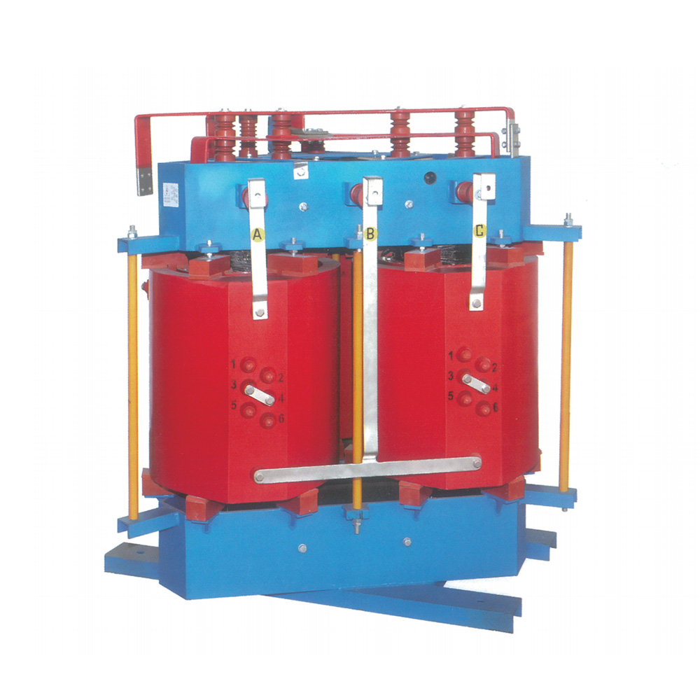
Electrical engineers categorize transformers based on how they modify the voltage between the input and output stages. Understanding these distinct categories helps you specify the exact equipment needed for your operational footprint.
A step up transformer receives electricity at a lower voltage and outputs it at a higher voltage. According to the laws of physics, as the voltage increases, the electrical current decreases proportionally. This inverse relationship is the secret to modern power grids.
You will primarily find these units at power generation sites. Traditional fossil-fuel power plants, massive solar farm arrays, and wind turbine installations rely heavily on step-up units. They take the generated electricity and amplify the voltage to hundreds of thousands of volts. Pushing electricity at high voltage and low current allows utilities to push power across hundreds of miles of transmission lines with minimal resistive heat loss.
In contrast, a step down transformer performs the exact opposite function. It receives high voltage from the grid and reduces it to a much safer, consumable level. As the voltage drops, the available current increases, providing the necessary amperage to run heavy machinery.
This is the standard solution for almost all commercial buildings, heavy manufacturing plants, and sprawling data centers. A facility might receive utility voltage at 4,160V or even 13.8kV. The step-down unit takes that dangerous incoming feed and converts it to usable equipment voltages like 480V for heavy motors, 240V for standard commercial equipment, or 120V for standard wall outlets and lighting circuits.
Not all transformers change the voltage. Isolation transformers feature a 1:1 winding ratio. The primary and secondary coils contain the exact same number of turns, meaning a 480V input yields a 480V output. Facilities use these specialty units strictly for safety, electrical noise reduction, and advanced grounding. You will often see them deployed in highly sensitive environments like hospital operating rooms, specialized medical imaging centers, and delicate data testing laboratories where even minor electrical noise causes severe equipment malfunction.
| Transformer Type | Voltage Change | Primary Application | Common Locations |
|---|---|---|---|
| Step-Up | Increases Output | Long-distance power transmission | Solar farms, wind installations, power plants |
| Step-Down | Decreases Output | Facility power distribution | Commercial buildings, factories, data centers |
| Isolation | No Change (1:1 Ratio) | Safety and noise filtering | Medical facilities, laboratories, server rooms |
Specifying a voltage conversion transformer requires strict attention to physical and electrical details. A poorly specified unit leads to frequent power trips, dangerous overheating, and non-compliance with commercial energy codes. You must evaluate several core criteria before making a final hardware selection.
Manufacturers rate transformers in kilovolt-amperes (kVA). This rating represents the maximum electrical load the unit can safely handle without exceeding its internal temperature limits. To determine your needed kVA, you must calculate the total amperage required by all connected facility equipment and multiply it by the operating voltage.
You must also forecast future facility expansion. Adding a new production line next year will require additional capacity. However, you must carefully mitigate sizing risks. Under-sizing your unit leads directly to severe overheating, rapid insulation degradation, and eventual catastrophic failure. Conversely, severely over-sizing the unit wastes upfront capital and forces the system to operate at poor efficiency levels. Most electrical engineers recommend sizing the unit so your typical continuous load runs at roughly 80% of the maximum kVA rating.
Because the induction process generates substantial heat, effective thermal management is mandatory. You generally choose between two primary cooling methods.
Modern electrical infrastructure must adhere strictly to mandatory energy efficiency codes. In the United States, for example, the Department of Energy (DOE) enforces the DOE 2016 efficiency standards. You must ensure any new unit meets or exceeds these baseline efficiency metrics.
When evaluating efficiency, you must look at two specific types of energy loss. "No-load losses" occur in the steel core just by having the unit energized, even if no facility equipment is running. "Load losses" occur in the copper or aluminum windings and increase as you draw more power through the system. Balancing these physical losses helps you maximize your daily energy savings and keep your utility bills predictable.
Understanding the theoretical transformer function means nothing if you install the hardware poorly. Physical installation dictates the long-term reliability and safety of your entire electrical system.
Space planning requires exact precision. You cannot simply drop a massive steel enclosure into a tight corner. You must factor in strict National Electrical Code (NEC) clearance requirements. The NEC mandates specific working space around the unit to ensure maintenance personnel can safely access the panels while energized.
You must also evaluate structural weight limits. A large liquid-filled unit can weigh tens of thousands of pounds, requiring a heavily reinforced concrete pad. Furthermore, you must plan clear ventilation pathways. Blocking the airflow to a dry-type unit will trigger thermal sensors and cause an abrupt facility shutdown.
These units require consistent, predictive maintenance to operate safely. Neglecting them leads to explosive failures. You should implement a standardized baseline for preventative maintenance.
Current industrial market realities heavily impact project timelines. Lead times for custom-built, brand-new transformers frequently extend to 50 or even 60 weeks depending on global steel and copper shortages. You must plan facility expansions a year in advance. To bypass these severe supply chain bottlenecks, many facility managers now evaluate the viability of reconditioned or remanufactured units. Reputable rebuilding facilities completely strip, rewind, and test legacy casings, delivering reliable hardware in a fraction of the time.
Purchasing an electrical transformer requires deep vendor scrutiny. Do not base your decision solely on a glossy product brochure. The supplier's engineering standards and post-sale support networks matter just as much as the copper coils inside the tank.
Never accept delivery of a high-voltage unit without demanding certified factory test reports. Reputable manufacturers run rigorous diagnostics before shipping. You should insist on documentation proving the unit passed all standard IEEE (Institute of Electrical and Electronics Engineers) and ANSI (American National Standards Institute) testing protocols. These tests verify the dielectric strength, confirm the exact voltage ratio, and prove the enclosure can withstand simulated lightning strikes and short-circuit faults.
Evaluate the warranty structures carefully. A standard 12-month warranty often contains loopholes. Does the warranty cover just the physical replacement parts, or does it also cover the specialized labor and heavy freight required to swap a 15,000-pound asset? Additionally, you must verify the availability of localized service networks. If a critical unit suffers a catastrophic failure at midnight on a holiday, you need a supplier capable of dispatching emergency field engineers and rapid replacement hardware.
Use a standardized technical checklist for final procurement. Ensure your engineering team confirms every detail:
An industrial electrical transformer does far more than execute basic voltage conversion. It fundamentally dictates the safety, energy efficiency, and future scalability of your entire commercial facility. Selecting the correct step-down or step-up unit ensures your heavy machinery receives clean, stable, and appropriately isolated power. Ignoring load calculations or cooling requirements leaves your operation highly vulnerable to equipment damage and dangerous arc flash incidents.
Before requesting quotes from suppliers, you should take immediate action to map your power needs. We strongly encourage buyers to conduct a comprehensive load profile study of their existing infrastructure. Consult with an experienced electrical engineer or a reputable supplier to match your exact technical specifications to your daily operational demands. Proper planning today prevents catastrophic downtime tomorrow.
A: Most well-built industrial units boast a lifespan of 20 to 30 years. However, this longevity remains heavily contingent on proper load management and strict adherence to preventative maintenance schedules, such as annual oil testing and thermal scanning.
A: Continuous overloading causes severe thermal degradation. The excessive heat bakes the internal paper insulation until it becomes brittle and cracks. This insulation failure inevitably leads to internal short circuits, potential fires, and catastrophic fault risks that can destroy downstream equipment.
A: While technically possible due to the physics of electromagnetic induction, it is highly dangerous. Safety codes and manufacturers strongly advise against reversing units unless they are explicitly designed and nameplate-rated for bi-directional power flow. It creates severe grounding and voltage regulation hazards.
A: The characteristic humming comes from a physical phenomenon called magnetostriction. The alternating magnetic field causes the internal steel core laminations to expand and contract slightly 60 times a second. While a steady hum is normal, a sudden, loud rattling indicates a mechanical issue requiring immediate maintenance.


