


Views: 0 Author: Site Editor Publish Time: 2026-09-20 Origin: Site


While the basic physics of step-up and step-down voltage remain constant, understanding exactly how oil transformer works is essential. This knowledge empowers you to make informed procurement and specification decisions. A basic metal box might look rugged outside. Inside, however, complex thermodynamic and electromagnetic dynamics are constantly at play. The efficiency of these internal mechanisms directly impacts load losses. Furthermore, they dictate the operational lifespan, safety compliance, and maintenance overhead for your facility. Ignoring these nuances often leads to expensive operational failures down the line. This guide bridges electrical theory and practical evaluation criteria. We detail the internal mechanics and component quality indicators you must verify. You will also learn about site-specific implementation risks and compliance factors. By the end, you will know how to evaluate structural integrity and fluid options confidently.
The primary working principle relies on electromagnetic induction, but performance is dictated by the precise engineering of the transformer core and winding.
The internal fluid serves a critical dual purpose, functioning simultaneously as transformer insulation oil (preventing arcing) and transformer cooling oil (dissipating heat).
Procurement evaluation must weigh different oil types (mineral vs. synthetic esters) against site safety requirements, environmental compliance, and budget.
Selecting the correct cooling classification (e.g., ONAN vs. ONAF) is a core decision that balances upfront CAPEX with long-term scalability and thermal management capabilities.
Every electrical system relies on fundamental physics. The oil immersed transformer working principle centers on Faraday’s Law of Induction. When you feed alternating current into the primary winding, it generates a fluctuating magnetic field. This shifting magnetic flux travels through the metallic core. It then intersects the secondary winding. This intersection induces a targeted, transformed voltage in the secondary circuit. It effectively steps power up for transmission or steps it down for safe distribution.
The efficiency of this electromagnetic transfer relies heavily on internal components. You must evaluate the transformer core and winding to understand unit performance.
Engineers design windings using either copper or aluminum conductors. Copper provides superior electrical conductivity. It allows manufacturers to build smaller, more compact units. Aluminum offers a lower initial purchase price but requires larger coils. Regardless of material, proper winding design mitigates I²R losses. We commonly call these copper losses. They occur because conductor materials naturally resist electrical flow.
The core serves as the physical pathway for the magnetic field. High-quality cores use laminated silicon steel. Manufacturers treat this steel to optimize grain orientation. They also slice it into ultra-thin laminations. This specific lamination thickness restricts stray electrical currents. By reducing these eddy currents and hysteresis effects, the core minimizes iron losses. Less iron loss means less wasted energy during operation.
Smart buyers never rely solely on marketing brochures. You should always request and review Factory Acceptance Test (FAT) data. This testing validates guaranteed load and no-load losses. No-load losses represent the energy consumed just to keep the core energized. Load losses occur under actual power demand. Reviewing this data ensures the unit meets your strict efficiency standards. It guarantees long-term energy savings over a 20- to 30-year operational lifecycle.
The internal fluid is not a passive component. It actively protects the entire electrical assembly. You cannot operate high-voltage equipment safely without it.
The fluid functions primarily as transformer insulation oil. It creates a robust barrier between the energized windings and the grounded metal tank. Without this barrier, electricity would arc across the gap. Such arcing causes catastrophic equipment failure. High dielectric strength is non-negotiable. The fluid must resist electrical breakdown under immense stress. Furthermore, it must repel ambient moisture. Even a tiny percentage of water contamination severely degrades its insulating capabilities.
Simultaneously, the fluid acts as transformer cooling oil. The core and coils generate intense heat during energy transfer. The surrounding fluid absorbs this thermal energy. As it heats up, its density decreases. The hot fluid naturally rises to the top of the tank. It then flows outward into exterior radiators. Cool air hits the radiators, dropping the fluid temperature. The denser, cooler fluid sinks back to the bottom. This continuous convection cycle prevents the internal components from melting.
You can choose from several fluid formulations. Each presents unique benefits and distinct limitations.
Mineral Oil (Naphthenic/Paraffinic): This remains the global industry standard. It provides excellent dielectric properties at a low cost. However, mineral oil is highly flammable and poses environmental risks if spilled.
Synthetic and Natural Esters: We classify these as fire-resistant fluids. They boast a significantly higher flash point. They are also biodegradable. These properties make them exceptionally safe for sensitive environments.
| Fluid Category | Fire Safety (Flash Point) | Environmental Impact | Budget Impact |
|---|---|---|---|
| Mineral Oil | Low (~140°C) | Toxic / Non-biodegradable | Highly Cost-Effective |
| Natural Esters | High (>300°C) | Fully Biodegradable | Premium Pricing |
| Synthetic Esters | High (>275°C) | Readily Biodegradable | Premium Pricing |
You must frame your oil selection around the facility location. Installing a unit indoors mandates strict fire safety compliance. Highly populated urban areas also dictate safer fluid choices. In these scenarios, you often must select ester-based oils. They satisfy stringent fire codes and strict insurance mandates. While esters require a higher initial budget, they drastically reduce facility risk profiles.
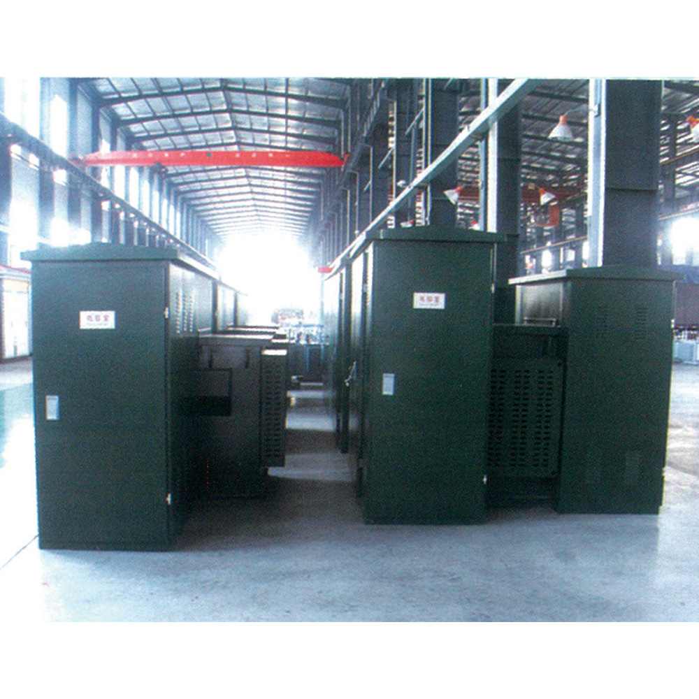
The internal mechanics require a fortress. The structural integrity of an oil filled transformer determines its survival in harsh environments.
The main steel tank houses the active components. It endures significant mechanical stress. Above the main tank sits the conservator. Thermal cycling causes the internal fluid to expand and contract constantly. The conservator acts as an expansion reservoir. When the unit heats up, excess fluid pushes into the conservator. When the unit cools, the fluid recedes. This protects the main tank from dangerous pressure ruptures.
As the conservator "breathes" air in and out, it risks pulling in ambient moisture. A silica gel breather prevents this contamination. The incoming air passes through the breather cartridge. The silica gel strips water vapor from the air before it touches the fluid. You must monitor the gel color. Once it saturates, maintenance teams must replace it. Alternatively, premium designs utilize sealed nitrogen blankets. The nitrogen fills the empty space, completely isolating the fluid from the outside atmosphere.
Effective thermal management requires surface area engineering. Radiators attach to the exterior tank walls. They feature multiple thin metal fins. These fins maximize the surface area exposed to ambient air. Better surface area design means faster heat dissipation. The hot fluid transfers its thermal energy through the steel fins into the surrounding atmosphere.
You should inspect several indicators of manufacturing rigor. Advanced anti-corrosion tank coatings are vital. If your facility sits near the ocean, demand C5-M marine-grade paint standards. Look for automated winding tension control during assembly. This ensures coils can withstand sudden short-circuit forces. Finally, examine the gasket materials. High-quality nitrile or Viton gaskets prevent long-term fluid leaks around bushings and access panels.
Thermal management defines capacity limits. You must match the specific cooling mechanism to your operational demands.
ONAN (Oil Natural Air Natural): This represents baseline reliability. Convection moves the hot fluid naturally. Ambient breezes cool the external radiators. It features zero moving parts. This method is ideal for stable, highly predictable load environments.
ONAF (Oil Natural Air Forced): This method adds auxiliary fans to the radiators. The fans force cool air across the metal fins. The fluid still circulates naturally via convection. It proves excellent for facilities expecting future capacity expansions or seasonal peak-load spikes.
OFAF/ODAF (Oil Forced Air Forced / Directed Air Forced): This premium tier uses internal mechanical pumps. The pumps actively circulate fluid through the core and into the radiators. High-speed fans blast air across the external fins. Engineers deploy this for high-capacity, space-constrained utility applications.
Guide your specifiers to balance the cooling method against your operational profile. Over-specifying cooling adds unnecessary complexity. For example, selecting an OFAF system for a small industrial plant introduces extra maintenance points. Pumps and fans eventually break down. Conversely, under-specifying leads to accelerated insulation degradation. If you run an ONAN unit beyond its thermal limits, the paper insulation burns out rapidly. Choose the classification that correctly balances initial budget with projected load growth.
Acquiring an oil transformer involves more than reviewing a spec sheet. Successful implementation requires regulatory diligence and site preparation.
You must establish a firm performance baseline. Emphasize the importance of IEEE C57.12.00 or IEC 60076 compliance. These global standards dictate strict testing protocols. They verify short-circuit withstand capabilities, temperature rise limits, and dielectric thresholds. Purchasing non-compliant equipment exposes your facility to severe safety risks. Always ask manufacturers for certified compliance documentation.
Consider the physical realities of installation early. A large liquid-filled unit poses environmental hazards. Local regulations typically mandate spill containment structures. You must construct concrete bund walls around the installation pad. If the tank ruptures, the bund catches the fluid before it contaminates groundwater. Additionally, plan for specialized rigging. These units are incredibly heavy. You will need high-capacity cranes and clear access routes for final placement.
Active systems require active monitoring. You must highlight ongoing maintenance requirements. Routine fluid filtration removes particulate matter and moisture. More importantly, schedule an annual Dissolved Gas Analysis (DGA). A DGA tests the fluid for trace gases like hydrogen or ethylene. Spikes in these gases indicate internal faults before they cause sudden failure. Consistent maintenance preserves warranty status and ensures operational safety.
Advise your buyers to prioritize transparent manufacturers. Shortlist vendors who provide exhaustive FAT loss data upfront. Look for partners who offer customized fluid options based on your site-specific risk assessments. Finally, demand a demonstrable track record. The manufacturer should prove successful deployments in your specific industry application. Experience matters when specifying mission-critical infrastructure.
An oil-immersed unit is not a passive metal box. It functions as an active thermodynamic and electromagnetic system. Internal components constantly manage high voltages, immense heat, and physical stress. Understanding these dynamics changes how you evaluate equipment.
Specifying the right unit requires a careful balancing act. You must align winding efficiency, specific fluid characteristics, and cooling mechanisms against your facility demands. You must weigh risk tolerance against available budgets. Do not cut corners on structural integrity or environmental compliance.
We encourage engineers and procurement teams to collaborate deeply. Share your specific load profiles, environmental conditions, and site constraints with technical sales teams. They can perform precise application sizing and generate accurate quotes. Diligent upfront planning guarantees decades of reliable power delivery.
A: Oil possesses superior heat capacity and much higher dielectric strength compared to air. Fluid absorbs and dissipates thermal energy rapidly. It also provides a stronger barrier against electrical arcing. This dual functionality enables manufacturers to build higher voltage ratings in a significantly smaller physical footprint.
A: With rigorous maintenance, the fluid typically lasts 15 to 20 years. This often mirrors the operational lifespan of the equipment itself. Achieving this longevity requires regular fluid filtration, proactive moisture control, and routine chemical testing to prevent acidic degradation over time.
A: Fluid-filled units offer superior cooling and rugged outdoor resilience for high-voltage applications. Dry-type units cool via natural air ventilation. Engineers generally restrict dry-type models to lower voltages and indoor applications. Dry-types meet strict fire safety profiles but struggle with extreme environmental exposure.
A: Dropping fluid levels expose the energized core and windings. This removes vital insulation and cooling. Exposed windings lead rapidly to catastrophic electrical arcing, severe overheating, and complete equipment failure. You must monitor liquid level gauges constantly to prevent sudden, destructive faults.


