


Views: 0 Author: Site Editor Publish Time: 2026-09-10 Origin: Site


When dealing with electrical hardware design, one fundamental question constantly arises: is a transformer AC or DC? Technically, fundamental transformers rely entirely on alternating current to function safely and properly. However, a major commercial disconnect exists in the market today. Many consumers and hardware engineers colloquially refer to power adapters, wall warts, and rectifiers simply as "transformers."
This loose terminology creates widespread industry confusion. It leads to mismatched electrical components, blown fuses, and costly procurement delays. Understanding the core physics behind power conversion matters immensely for project safety. In this comprehensive guide, we will clarify these physical limitations. We will decode component nameplates to help you identify hardware accurately. You will also learn a practical framework for selecting the correct power conversion hardware for your specific application. By the end, you will know exactly when to specify raw magnetic components versus fully regulated power supplies.
Strictly AC: At a fundamental physics level, a true transformer only operates with AC due to the requirement for a continuously changing magnetic field.
The DC Risk: Applying a constant DC voltage to a standard transformer's primary coil will act as a short circuit, potentially causing overheating, blown fuses, or component failure.
Market Misnomers: Commercially sold "AC-DC transformers" are actually combination devices containing a standard AC transformer followed by a rectifier circuit to convert the output to DC.
Selection Criteria: Choosing between an AC transformer, a Switch-Mode Power Supply (SMPS), or a DC-DC converter depends on required galvanic isolation, efficiency targets, and load stability.
To fully grasp the transformer working principle, you must first look at Faraday’s Law of Induction. This physical law dictates how magnetic fields interact with electrical circuits. When electrical current flows through a copper wire, it naturally creates a magnetic field. If you change this current over time, the magnetic field fluctuates. This changing magnetic field then induces a proportionate voltage in a nearby secondary coil. The entire process relies on continuous change.
An alternating current transformer perfectly accommodates this requirement. Standard electrical grids provide 50Hz or 60Hz sine waves. These sine waves continuously reverse direction. They naturally provide the constant fluctuation needed for magnetic induction. You do not need internal moving parts to achieve this. You also avoid complex, failure-prone switching electronics. The device handles high-power transfers smoothly and reliably through magnetic coupling alone.
This purely magnetic transfer creates a crucial feature called galvanic isolation. The primary input circuit and the secondary output circuit remain physically separated. No direct electrical path exists between them. This feature prevents dangerous ground loops and electrical faults. Medical devices heavily rely on this strict isolation. Industrial electronics also depend on it to meet rigid safety compliance standards. Without alternating current driving the magnetic flux, this elegant isolation method fails completely.
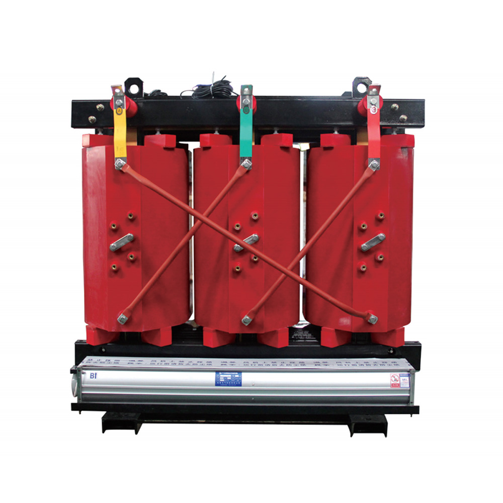
Hardware enthusiasts frequently ask, can transformer work on DC? The short answer is no. You cannot operate them under pure, steady-state conditions without severe consequences.
Applying a steady DC voltage to a primary winding removes the fluctuating magnetic field. Without a changing field, no secondary voltage induces. The primary coil loses its inductive reactance. It simply acts as a long piece of wire with very low resistance. According to Ohm's Law, this creates a dead short circuit. The coil draws massive amounts of current rapidly. This situation inevitably leads to thermal runaway. Copper wires melt, fuses blow, and severe fire hazards emerge. You must never apply constant DC directly to standard magnetic coils.
However, minor engineering exceptions exist in modern electronics. Transformers can handle pulsed or fluctuating DC. We frequently see this behavior in specialized audio electronics. You also see it with flyback transformers inside switch-mode power supplies. In these specific designs, transistors rapidly turn the DC voltage on and off. As long as the current constantly changes, magnetic induction still occurs safely.
Stepping steady DC voltages up or down requires distinct hardware. You cannot achieve this using a bare magnetic component. You need a dedicated DC-DC converter. These sophisticated units use internal oscillators or switching ICs. They chop the incoming DC into high-frequency pulses. They push those pulses through a small magnetic core. Finally, they smooth the output back into steady DC.
The consumer electronics marketplace heavily mislabels power components. People purchase "AC-DC transformers" daily for laptops and appliances. However, these are combination devices, not raw components. They contain multiple internal stages to achieve the final direct current output.
Let us break down the internal anatomy of a typical commercial power supply. Understanding these stages clarifies the technology.
Stage 1: AC step-down. An actual AC transformer first lowers the dangerous main grid voltage. It reduces 120V or 240V down to a safer working level like 12V or 24V.
Stage 2: Rectification. A bridge rectifier steps in next. Diodes within this circuit convert the raw alternating sine wave into pulsating direct current.
Stage 3: Filtering. Large electrolytic capacitors smooth out the rough, pulsating waves. They fill in the voltage gaps to create a much more stable baseline.
Stage 4: Regulation. Dedicated integrated circuits monitor the output. They maintain a perfectly steady DC voltage regardless of fluctuating downstream loads.
Terminology matters deeply for engineering and procurement teams. Precision in language saves money and prevents disaster. If you request a "transformer" from a procurement supplier, they might ship a raw AC-AC component. If your circuit board actually requires a regulated DC power supply, your project halts. Miscommunications like this lead to costly hardware incompatibilities. They also cause massive project delays while teams wait for replacement components.
Before you plug any electronic load in, you must positively identify the output voltage type. Relying on guesswork often destroys sensitive microelectronics instantly. You should follow a systematic identification process.
First, rely on visual and nameplate verification. Manufacturers print specific compliance labels on quality hardware.
AC Indicators: Look closely at the output specification section. You might see "VAC", "V~", or a distinct wavy line symbol (~). These guarantee an alternating output.
DC Indicators: Check the label for "VDC", "V-", or a solid line positioned over a dashed line. Clear polarity symbols (+/-) near the connector also confirm a direct current output.
Next, use standard multimeter testing best practices. Bench testing provides undeniable proof when labels rub off. Follow this safe diagnostic logic:
Set your digital multimeter to measure AC voltage initially.
Carefully probe the active output terminals.
If the display shows a stable voltage, you have an alternating supply.
If the reading hovers near zero, safely switch your meter to DC voltage mode.
A clear, stable reading in this mode confirms you have a rectified supply.
Finally, observe physical form factor clues. Physical traits offer excellent preliminary hints. Heavy, simple iron-core blocks are almost always basic AC-AC units. They require dense metals for low-frequency magnetic coupling. Lighter, fully enclosed plastic blocks generally house switch-mode power supplies. They use tiny, high-frequency ferrite cores instead of heavy iron.
Choosing the right hardware requires a highly systematic approach. Engineers must evaluate several critical factors before finalizing their power distribution designs. Picking the wrong topology causes efficiency losses and premature failures.
First, identify your exact load requirement. Ask yourself what the downstream hardware specifically demands. Do transformers work with AC components directly? Yes, they absolutely do. Certain industrial HVAC contactors operate on pure alternating current. Halogen lighting fixtures and vintage audio gear also thrive on pure stepped-down voltage. Conversely, modern microcontrollers, delicate LED arrays, and precision sensors demand tightly regulated DC. Feeding these sensitive components raw alternating waves will destroy them instantly.
Next, evaluate your efficiency and space constraints. You must balance physical size against electrical performance. Linear power supplies pair a heavy magnetic core with a basic rectifier circuit. They offer extremely low electrical noise. However, they take up significant enclosure space and weigh heavily. Switch-Mode Power Supplies operate entirely differently. They are highly compact and extremely efficient. Unfortunately, their high-speed switching transistors introduce high-frequency electrical noise. You must filter this noise out for sensitive analog applications.
You must also plan for scalability and thermal management. Evaluate your operating enclosure carefully. Linear units generate substantial heat during operation. SMPS units run much cooler, but they still require adequate ventilation space. Proper thermal management prevents premature component failure inside sealed utility boxes.
Finally, verify regulatory compliance and safety standards. Always source properly certified components. Look for recognized marks like UL or CE. For medical applications, you must ensure strict IEC 60601-1 certification. These rigorous standards guarantee proper galvanic isolation. They also verify exceptionally low leakage currents, keeping human operators safe from electric shock.
Table: Power Component Selection Comparison
| Feature / Requirement | Linear Power Supply (AC-DC) | Switch-Mode Power Supply (SMPS) | Raw Component (AC-AC) |
|---|---|---|---|
| Output Type | Regulated DC | Regulated DC | Pure AC |
| Physical Size & Weight | Heavy and Bulky | Lightweight and Compact | Heavy (Iron Core) |
| Electrical Noise | Very Low (Ideal for Audio) | Moderate to High (Needs Filtering) | Very Low |
| Energy Efficiency | Low (Generates Excess Heat) | High (Often >85%) | High (Up to 98% in ideal conditions) |
| Primary Application | Sensitive Analog Electronics | Computers, LEDs, Digital Circuits | HVAC Contactors, Halogen Lamps |
True transformers remain fundamentally tied to alternating current physics. They require fluctuating magnetic fields to induce voltage safely. However, the broader commercial market uses the term loosely. People constantly use it to describe fully integrated power adapters. You must cut through this terminology fog to ensure safe engineering practices.
Always verify your specific circuit requirements carefully. Determine if your load requires raw stepped-down AC or a rectified, filtered DC output. Do this before authorizing any purchase orders or finalizing expensive circuit board layouts. Trusting casual terminology often leads to destroyed hardware and project failures.
We highly recommend consulting individual component datasheets for exact electrical specifications. Never guess when dealing with line voltages. If you face complex hardware integration challenges, take action immediately. Contact a specialized power component supplier for tailored, application-specific guidance.
A: It takes AC from the wall and outputs DC to the laptop. Technically, it is an AC-DC Switch-Mode Power Supply (SMPS), not just a raw magnetic component. Calling it a transformer is a common industry misnomer.
A: It can cause permanent damage to sensitive DC electronics like microcontrollers or LEDs. This damage happens rapidly due to reverse voltage phases and a complete lack of voltage regulation.
A: Alternating current can be easily stepped up to very high voltages by basic magnetic components. This process enables highly efficient long-distance power transmission. The power is then safely stepped down for residential use.
A: Yes, you can achieve this easily. You must wire a proper bridge rectifier and a smoothing capacitor directly to the secondary output terminals. This circuit will convert the alternating wave into stable DC.


