


Views: 0 Author: Site Editor Publish Time: 2026-07-02 Origin: Site


The step-up transformer serves as the critical grid gateway between solar inverters and your medium-voltage collection network. It dictates the reliability of power export for the entire generation facility. A failure at this junction halts production instantly.
Standard distribution transformers often fall short for utility-scale solar applications. They struggle under unique daily load profiles. They face extreme thermal stress. High-frequency inverter harmonics also degrade standard insulation prematurely. Furthermore, remote environments subject these units to severe weather and dust ingress. Relying on off-the-shelf equipment introduces massive operational risks and invites catastrophic downtime.
This guide delivers an evidence-based framework for specifying specialized electrical infrastructure. We will evaluate core configurations, analyze performance metrics, and outline proven procurement strategies. You will learn how to select robust equipment tailored precisely for utility-scale PV deployments.
Utility-scale solar demands transformers engineered for cyclic loading, inverter-driven harmonics, and reverse power flow.
Selecting the right dielectric fluid (e.g., natural esters) mitigates environmental risks and fire hazards while impacting footprint sizing.
Effective evaluation requires balancing initial CapEx with total cost of ownership (TCO), particularly regarding no-load losses.
Vetting manufacturers on their supply chain transparency, Factory Acceptance Testing (FAT) rigor, and IEEE/ANSI compliance is critical to avoiding project delays.
Solar arrays present a highly specific set of electrical and environmental challenges. Understanding these operational realities is the first step in specifying the right equipment.
Solar generation profiles follow extreme diurnal cycles. Output drops to absolute zero during the night. It ramps up rapidly in the morning. It peaks sharply precisely at midday. This aggressive cycling causes intense thermal expansion and contraction within the core and windings. Over time, this thermal stress accelerates insulation degradation. It demands robust thermal management systems and upgraded internal components capable of enduring daily temperature spikes.
Modern central and string inverters introduce high-frequency harmonics into the system. These non-linear loads create localized hot spots within standard winding structures. You must account for this by incorporating electrostatic shielding. Shielding effectively isolates the grid from transient voltage spikes and high-frequency noise. Specialized winding designs also mitigate these harmful eddy currents. They prevent premature failure and ensure stable power quality.
Grid-tied solar sites frequently experience reverse power flow. Power moves from the wider grid back into the local system during periods of low generation. Your chosen Pad Mounted Transformer must manage this bidirectional flow seamlessly. It must do so without compromising voltage regulation. Maintaining tight voltage control ensures local grid stability and prevents costly trip events.
Developers usually build utility-scale solar farms in remote, exposed locations. Equipment faces intense ultraviolet radiation, extreme temperatures, and high winds. Baseline specifications must mandate heavy-duty UV-resistant coatings. Seismic ratings must match regional geological risks. Proper ingress protection is non-negotiable. NEMA 3R or NEMA 4 enclosures shield internal components from driving rain, snow, and airborne dust.
Selecting the optimal physical and electrical configuration directly impacts site layout, safety protocols, and installation budgets.
Engineers must choose between radial and loop feed topologies based on the array design.
Radial Feed: This design suits isolated string inverter setups perfectly. It isolates faults easily because each unit connects independently. However, it requires significantly more underground cabling, which increases material costs.
Loop Feed: This configuration allows you to daisy-chain multiple stations together. It drastically reduces overall cabling requirements across expansive PV arrays. It provides better redundancy and lowers installation expenses for large-scale operations.
The choice of high-voltage termination affects both safety and enclosure sizing.
Dead-Front: These designs feature fully insulated, grounded connections. They maximize operator safety during routine maintenance. They also allow for a smaller physical footprint due to reduced electrical clearance requirements.
Live-Front: These configurations expose the high-voltage connections. They make visual inspections much easier for maintenance crews. However, they demand larger enclosures and mandate much stricter safety protocols during servicing.
Choosing between copper and aluminum windings involves weighing initial costs against long-term operational efficiency.
Winding Material Performance Comparison Chart
| Material Type | Upfront Cost | Conductivity & Efficiency | Physical Footprint | Thermal Expansion Profile |
|---|---|---|---|---|
| Aluminum | Lower initial investment | Good, but requires larger cross-sections | Requires larger core and tank size | Higher expansion; requires specialized bracing |
| Copper | Higher initial investment | Superior; minimal resistance losses | Highly compact and space-efficient | Low expansion; highly durable under load cycling |
The insulating fluid plays a massive role in cooling, safety, and environmental compliance.
Mineral Oil: The industry standard for decades. It offers excellent cooling and a lower initial purchase price. However, it requires extensive concrete containment basins due to high flammability and soil contamination risks.
Natural and Synthetic Esters (e.g., FR3): These fluids boast a remarkably high flash point. They are fully biodegradable. This often eliminates the need for expensive structural containment. While they carry a higher upfront cost, they improve fire safety and reduce necessary clearance distances.
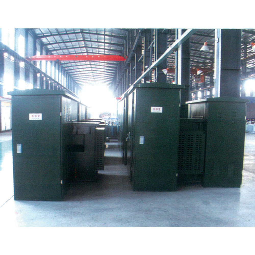
Making informed procurement decisions requires evaluating efficiency metrics, standardization options, and smart grid readiness.
You must evaluate electrical losses against the specific solar generation profile. No-load losses, or core losses, occur continuously, 24 hours a day. Load losses, or winding losses, scale directly with the current generation output. Since solar farms only peak for a few hours daily, optimizing the balance between core and winding losses is vital. Prioritizing low core losses often yields better lifecycle energy efficiency.
Project developers often debate utilizing standardized Pad Mounted Transformer Solutions versus custom-engineered units.
Standard off-the-shelf units offer faster delivery timelines. They simplify spare parts inventory.
Custom-engineered solutions match unique site topologies flawlessly. They accommodate specific multi-winding requirements for complex central inverters perfectly.
Authoritative certifications guarantee safety and performance. You must verify compliance with IEEE C57.159, which is the specific guide for application in PV systems. Ensure equipment meets rigorous ANSI and CSA structural standards. Furthermore, verify adherence to Department of Energy (DOE) efficiency mandates to avoid regulatory penalties and ensure optimal performance.
Modern renewable energy sites require constant oversight. You should mandate integrated monitoring systems. Liquid level gauges, pressure sensors, and temperature monitors are essential baseline requirements. Ensure these gauges support SCADA connectivity. Remote monitoring prevents minor anomalies from cascading into catastrophic equipment failures.
Executing a utility-scale solar project requires flawless logistical planning. Overlooking transportation or permitting details will derail strict EPC schedules.
Global electrical supply chains remain highly volatile. You must assess supplier delivery timelines with extreme scrutiny. Order critical infrastructure during the earliest phases of project engineering. Build buffer periods into your EPC project schedules. Proactive procurement avoids disastrous bottlenecks during the final construction phases.
Labor shortages continue to plague the construction industry. Skid-mounted solutions address this issue directly. Manufacturers pre-assemble the inverter, step-up equipment, and medium-voltage switchgear onto a single structural skid. This integration drastically reduces on-site labor hours. It streamlines complex wiring tasks and accelerates the overall installation timeline.
Heavy electrical equipment demands specialized logistical planning. You must factor physical dimensions and total weight into your procurement phase. Remote solar sites often feature unpaved roads and limited heavy crane access. Confirm route clearances and bridge weight limits well before scheduling delivery.
Environmental compliance heavily influences site preparation costs. Traditional mineral oil requires extensive spill prevention, control, and countermeasure (SPCC) plans. You must build concrete containment basins to satisfy regulators. Utilizing biodegradable ester fluids simplifies SPCC requirements. It often eliminates the need for expensive secondary containment structures entirely.
Not all manufacturers possess the engineering capability required for renewable energy applications. A rigorous vetting process protects your investment.
General distribution manufacturing experience does not equal solar step-up expertise. You need partners who understand inverter duty profiles deeply. Ask potential suppliers for case studies detailing specific utility-scale PV deployments. Verify their track record in handling aggressive diurnal cycling and non-linear loads.
Never bypass Factory Acceptance Testing. You must demand rigorous FAT protocols before authoring shipment releases. Heat run tests verify the unit operates safely within thermal limits. Induced overvoltage tests confirm the integrity of internal insulation. Harmonic loss measurements guarantee the equipment will handle non-linear inverter loads without overheating.
Utility-scale solar farms operate for 25 to 30 years. Evaluate warranty terms against this expected lifespan. Ensure the manufacturer offers comprehensive post-deployment support. Rapid access to replacement parts and specialized field technicians minimizes revenue loss during unexpected outages.
Transitioning from evaluation to procurement requires structured documentation. Use this document checklist for your Request for Proposal (RFP) submissions:
Provide highly detailed single-line electrical diagrams.
Submit comprehensive site environmental data, including temperature extremes and altitude.
Include exact inverter specifications, noting specific harmonic distortion profiles.
Detail the exact communication protocols required for seamless SCADA integration.
Specifying electrical infrastructure for utility-scale solar is a critical risk-mitigation exercise. It is never a simple commodity purchase. Your equipment must withstand extreme daily thermal cycling. It must isolate aggressive inverter harmonics. It must survive punishing environmental conditions seamlessly.
Aligning your specifications directly with specific inverter outputs guarantees operational stability. Matching internal configurations to your site-specific load profiles maximizes long-term energy yields. This precise engineering alignment reduces lifecycle expenses and ensures your facility exports power reliably for decades.
Take action on your project today. Consult with expert technical sales engineering teams to review your requirements. Submit your single-line diagram for a comprehensive architectural review. Download a technical sizing specification sheet to begin framing your upcoming RFP.
A: Standard distribution transformers serve relatively steady loads. Solar step-up units handle extreme daily thermal cycling as production ramps up and down. They include specialized electrostatic shielding to block harmful inverter harmonics. These custom designs also feature robust cooling systems to manage non-linear loads and reverse power flows safely.
A: Central inverters typically require complex multi-winding configurations. They need dedicated low-voltage inputs for each specific inverter block. String inverters aggregate power earlier in the circuit. This allows you to use standard dual-winding designs. Your chosen inverter architecture directly dictates internal winding complexity and external bushing arrangements.
A: Current lead times generally range between 40 to 60 weeks. Global supply chain volatility heavily impacts raw material availability, especially for specialized core steel. You should always initiate procurement during the earliest engineering phase. Proactive planning prevents costly delays in your overarching construction and commissioning schedules.
A: Electrostatic shielding physically isolates the primary and secondary windings. It prevents high-frequency noise and harmful voltage transients from passing through. Inverters constantly generate these non-linear harmonics. Proper shielding protects the wider utility grid from interference and dramatically extends the operational lifespan of the unit's internal insulation.


