


Views: 0 Author: Site Editor Publish Time: 2026-07-27 Origin: Site


Highway construction projects demand rugged temporary power networks spanning linear, geographically extended, and environmentally harsh sites. Delivering stable electricity across miles of active roadwork poses immense logistical hurdles. Without robust electrical infrastructure, heavy civil operations grind to an absolute halt.
Unfortunately, standard commercial transformers often fail prematurely under the heavy dust, vibration, and dynamic load conditions typical of roadwork. These predictable hardware failures inevitably trigger costly project delays and safety hazards. You must bridge this reliability gap to keep infrastructure projects strictly on schedule.
In this guide, we provide electrical engineers, project managers, and procurement teams an evidence-based framework for evaluating equipment specifications. You will discover practical methods to finalize smart procurement decisions for temporary highway power systems. We will show you exactly how to navigate complex load profiles and hostile environmental variables successfully.
Proper sizing for highway projects must account for high inrush currents from heavy machinery alongside continuous baseline loads (e.g., site lighting).
Selecting NEMA 3R, 4, or 4X enclosures is non-negotiable for mitigating ingress from weather, concrete dust, and vehicular vibration.
Skid-mounted and dry-type transformers offer the highest mobility-to-durability ratio for phased, linear construction sites.
Compliance with state DOT guidelines (e.g., Caltrans) and IEEE standards limits liability and ensures rapid utility grid interconnection.
Highway construction environments present unique electrical distribution challenges. You cannot treat a fifty-mile highway expansion like a standard commercial building site. The operational footprint constantly shifts. Equipment endures extreme physical punishment daily. Understanding these specific site conditions forms the foundation of reliable power system design.
Managing significant voltage drop across miles of temporary cabling requires strategic planning. Highway projects stretch utility feeds to their absolute limits. You must push power from a single utility interconnect down a long corridor. This distance naturally causes voltage to sag. Engineers mitigate this by deploying step-up transformers at the power source. They then use step-down transformers closer to the active work zones. This dual-node strategy keeps voltage levels stable at the point of use.
You must distinguish between continuous base loads and intermittent high-draw loads. Continuous loads include security lighting, temporary traffic signals, and site trailers. These draw a predictable, steady current. Conversely, heavy equipment introduces chaotic demand spikes. Tunnel boring machines, large dewatering pumps, and portable batch plants require massive starting currents. A poorly specified temporary grid will trip breakers when a large pump kicks on. You need equipment capable of riding out these aggressive temporary spikes.
Roadwork sites subject electrical equipment to severe abuse. We must evaluate the impact of continuous mechanical vibration on core and coil longevity. Heavy excavators and compactor rollers generate constant seismic-like tremors. Standard commercial units will literally shake apart under these conditions. Extreme temperature fluctuations also stress insulation materials. High particulate matter, especially asphalt and concrete dust, coats internal components. This dust restricts airflow and causes dangerous heat buildup.
The ultimate goal is straightforward. We want to achieve zero unplanned downtime due to thermal overload or ingress failure during the project lifecycle. Every hour of lost power halts heavy machinery. Idle crews and equipment cost contractors thousands of dollars per hour. A reliable power network directly protects project profitability and timelines.
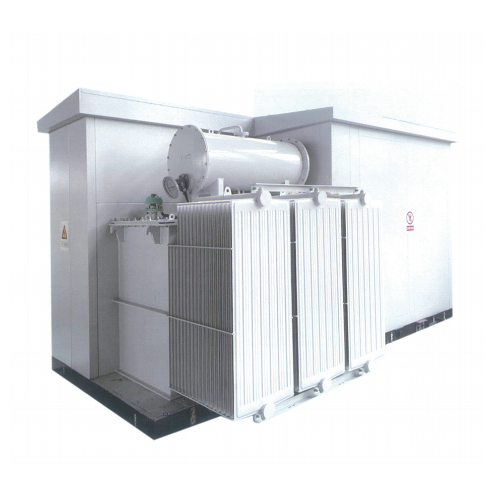
Technical specifications dictate how well equipment performs in the field. Procurement teams must look beyond basic nameplate ratings. You must align the internal engineering of the unit with the harsh realities of civil construction. Smart Transformer Selection directly prevents catastrophic field failures.
Accurate capacity calculation prevents dangerous thermal overloads. You begin by calculating the continuous baseline capacity. Engineers typically apply standard safety margins to this figure. The industry norm is specifying 125% of the expected continuous load. However, highway work requires an extra step. You must calculate the high inrush current tolerance for large motors. A dewatering pump might draw five times its running current during startup. The transformer must supply this brief surge without dropping the voltage for other connected equipment.
Temporary utility drops in remote areas rarely deliver perfect voltage. You must evaluate primary and secondary voltage requirements carefully. We strongly recommend specifying primary taps. Standard tap configurations include +/- 2.5% or 5% adjustments. If the local grid delivers low voltage, you adjust the tap to boost the secondary output. This mechanical adjustment compensates for utility voltage fluctuations effectively. It ensures your sensitive site equipment receives clean, usable power.
The choice between aluminum and copper windings sparks frequent debate. Both materials conduct electricity effectively, but they perform differently under stress. You must weigh physical resilience against procurement budgets.
| Material Type | Primary Advantages | Best Highway Applications |
|---|---|---|
| Copper Windings | Better fault-current withstand, superior thermal conductivity, higher mechanical strength. | High-vibration zones, heavy motor starting loads, space-constrained deployments. |
| Aluminum Windings | Cost-efficiency, significantly lower overall unit weight. | Highly mobile skid units, baseline continuous loads (lighting arrays). |
Copper offers better fault-current withstand and compactness. It handles physical vibration and sudden heat spikes exceptionally well. Aluminum provides noticeable cost-efficiency at lower weights. Lighter units are easier to relocate along the highway corridor. We recommend copper for critical heavy-load nodes and aluminum for general lighting distribution.
Impedance dictates how much current flows during a short circuit. You must ensure transformer impedance aligns with downstream breaker ratings. If the impedance is too low, a fault could deliver a massive current spike. This spike can easily destroy downstream panels and melt cabling. Proper matching safely manages short-circuit fault currents without over-specifying equipment. It creates a coordinated protection scheme for the entire temporary grid.
Standard indoor electrical equipment has no place on a highway project. Environmental ingress destroys unprotected electronics rapidly. Furthermore, non-compliant equipment opens contractors to severe legal liabilities and utility rejection.
You must move well beyond basic indoor ratings. Sourcing the correct enclosure depends entirely on specific regional climates. NEMA 3R provides a baseline weather-resistant housing. It protects against rain, sleet, and external ice formation. However, NEMA 3R is not airtight. For projects generating heavy concrete dust or facing coastal salt spray, NEMA 4 or NEMA 4X is necessary. These watertight and corrosion-resistant housings block all particulate ingress. They keep internal components clean and dry.
Transformers generate significant heat that needs to escape. We must assess natural air convection (AN) versus forced air (AF). Forced air uses external fans to blow air across the coils. This increases capacity but introduces a critical vulnerability. Fans suck abrasive dust directly into the enclosure. Natural convection relies on passive heat rising. It uses no moving parts. Natural convection is often preferred in temporary setups to minimize moving parts susceptible to dust clogging.
Compliance is mandatory, not optional. You must navigate DOT-specific electrical guidelines carefully. State agencies like Caltrans maintain strict rules regarding temporary highway power. Equipment must also meet IEEE C57 standards for distribution transformers. Finally, local utility interconnect requirements dictate how you attach to their grid. Failing to meet these standards guarantees the utility will refuse to energize your site.
Temporary setups pose severe electrocution risks if grounded poorly. Mandatory adherence to NEC Article 450 is just the starting point. You must implement strict temporary grounding protocols to protect on-site personnel. Earth shifts, muddy conditions, and heavy machinery alter grounding paths constantly. We must mitigate step-and-touch voltage risks near temporary substations. Driving deep ground rods and bonding all metal enclosures prevents fatal shocks during electrical faults.
Form factor determines how easily crews can deploy and maintain the equipment. You need configurations built for rapid movement and brutal handling. Finding the right Transformer Selection Solutions drastically reduces field labor costs.
The cooling medium significantly impacts deployment logistics and environmental safety.
Dry-Type: These units use ambient air for cooling. They are generally preferred for temporary, highly mobile deployments. They pose absolutely zero spill risk. If a forklift punctures the enclosure, you do not face an EPA hazardous materials cleanup. They offer simple, straightforward ease of maintenance.
Liquid-Filled: These use dielectric oil for heat dissipation. They handle massive loads and harsh weather efficiently. However, they are evaluated only for highly specific, high-capacity semi-permanent substations where extreme cooling is required. Moving them risks oil spills, demanding expensive containment berms.
Mobility drives highway construction efficiency. We highly recommend reviewing modular systems equipped with pre-wired primary fused disconnects and secondary breaker panels. Manufacturers mount these entire assemblies on heavy-duty steel skids or road-ready trailers. These packaged systems reduce on-site commissioning time from days to hours. Electricians simply land the primary feed and plug in the downstream loads. They enable rapid relocation as the highway phase advances down the corridor.
Even within dry-type categories, you have choices regarding internal protection. Ventilated units rely on louvers to let air circulate. Encapsulated units fill the entire core and coil assembly with solid epoxy resin. We advise using epoxy-encapsulated dry-type transformers for low-kVA localized loads. For example, temporary toll gantry testing requires clean power but low capacity. Encapsulation completely seals out moisture and corrosive dust. It creates a virtually indestructible block of power distribution.
Procuring heavy electrical equipment requires strategic foresight. Even the perfect technical specification fails if the unit arrives three months late. You must vet vendors thoroughly to ensure project continuity.
Global electrical supply chains remain highly constrained. You must factor in current manufacturing lead times against aggressive construction schedules. Custom-engineered units often require six to eight months for delivery. We suggest evaluating readily available modular units versus custom builds. Standardized skid-mounted systems are frequently kept in stock by specialized rental and sales fleets. Leveraging standard configurations keeps your project on track.
Never accept a transformer onto a job site without proof of performance. Transit vibration frequently damages internal connections. You must require factory acceptance testing (FAT) reports before the unit ships. Once it arrives, electricians must perform specific field checks. We require megger testing to verify insulation integrity. You must also demand turn-ratio verification prior to site delivery. These tests confirm the unit survived transport and will operate safely when energized.
Your supplier acts as a critical project partner. Shortlist vendors based on strict operational criteria.
Robust Warranty Terms: Look for warranties that explicitly cover temporary construction environments, not just clean indoor usage.
Technical Support Availability: Ensure the vendor provides immediate phone support for field troubleshooting. Downtime at 2:00 AM requires instant answers.
Demonstrable Experience: Vet their track record in heavy civil infrastructure. They should understand DOT regulations natively.
Replacement Inventory: Verify they hold emergency swap-out stock in case of a catastrophic lightning strike or physical accident.
Effective specification relies on balancing rugged environmental protections with precise electrical sizing. Highway construction sites push equipment to extreme limits. You must protect against dust, vibration, and weather while handling dynamic motor loads. Focusing on NEMA-rated enclosures, appropriate tap changers, and modular skid-mounted designs ensures continuous site power.
Procurement and engineering teams should immediately finalize their load calculations. Take the time to map your linear site distribution plan clearly. Identify your step-up and step-down nodes. Finally, issue your RFQs strictly demanding compliance with the identified NEMA and IEEE standards. Demanding ruggedized, pre-tested equipment is the surest way to keep your heavy civil project powered and profitable.
A: Typically, engineers apply a 125% multiplier to the continuous load. They also separately calculate the maximum starting kVA of the largest single motor on site. This dual-calculation approach ensures the equipment can handle massive inrush currents from pumps or boring machines without causing damaging voltage dips.
A: It is highly discouraged. Commercial units lack the robust NEMA 3R/4 enclosures and vibration-resistant mounting necessary to survive a civil construction environment. Dust ingress and physical shaking quickly compromise standard coils, leading to exceptionally high failure rates and project delays.
A: They combine the transformer, primary disconnect, and secondary distribution into a single, pre-wired, forklift-ready unit. This integrated design drastically reduces on-site electrical labor costs. It also allows crews to rapidly relocate the entire power node as the active job site moves down the highway.
A: Long cable runs cause significant voltage drop. Engineers often utilize step-up transformers at the power source and step-down transformers near the load. They combine this layout with adjustable primary voltage taps to manually boost lagging voltage, delivering clean, usable power at the end of the line.


