


Views: 0 Author: Site Editor Publish Time: 2026-09-30 Origin: Site


Specifying and procuring high-voltage infrastructure represents a high-stakes capital expenditure. In these demanding environments, operational reliability directly dictates your facility's uptime, safety, and overall success. Buyers often struggle to balance upfront procurement costs against long-term maintenance liabilities and strict environmental compliance. You might find it challenging to objectively evaluate liquid-filled units versus dry-type alternatives for your specific site constraints.
This comprehensive guide provides a detailed technical and commercial evaluation framework. Engineers, project planners, and procurement managers will learn how to confidently specify, assess, and shortlist the right transformer for their power system. We will explore advanced cooling mechanics, categorize different grid designs, and evaluate key operational advantages. By following these targeted insights, you can secure robust infrastructure carefully aligned to your operational goals and strict regulatory obligations.
Effective transformer oil cooling enables significantly higher voltage capacities and better thermal management than dry-type equivalents.
Selecting between oil transformer types requires matching grid capacity, installation environment, and load volatility.
Procurement should be driven by rigorous Factory Acceptance Testing (FAT) and verified load loss metrics, not just nameplate ratings.
Understanding internal thermal dynamics reveals why liquid-filled infrastructure dominates high-voltage applications. Internal fluid serves dual purposes inside the tank. It absorbs intense heat generated by the magnetic core and copper windings during operation. The fluid then transfers this heat to external radiators for dissipation into the surrounding atmosphere. Proper transformer oil cooling ensures internal components remain within safe operating temperatures, preventing premature insulation failure.
Engineers classify these cooling mechanisms by circulation methods. Oil Natural Air Natural (ONAN) relies purely on thermal convection. Hot fluid naturally rises, cools in the radiators, and sinks back down. Oil Natural Air Forced (ONAF) adds external fans to accelerate heat dissipation during peak loads. These robust circulation methods grant liquid-filled units their incredible overload capacities.
Beyond thermal management, the fluid acts as a critical dielectric insulator. High-voltage environments create immense electrical stress. The liquid boasts exceptionally high dielectric strength, which actively prevents dangerous electrical arcing and corona discharge between internal components. Air simply cannot match this insulating density.
Modern grid operators now choose between different insulating fluids based on site requirements.
Traditional Mineral Oils: These remain the industry standard. They offer excellent electrical properties and thermal stability at a baseline cost. However, their lower flashpoint requires strict fire safety spacing.
Natural Ester Fluids: Derived from vegetable oils, these liquids improve environmental compliance through high biodegradability. They also boast elevated flashpoints, making them less flammable.
Synthetic Ester Fluids: These highly engineered liquids provide extreme oxidative stability and fire resistance. Operators often select them for highly restricted indoor vaults or offshore platforms.
Common Mistake: Do not assume all fluids are interchangeable. Retrofilling a mineral oil tank with ester fluid requires careful engineering analysis, as esters possess different kinematic viscosities that alter heat dissipation rates.
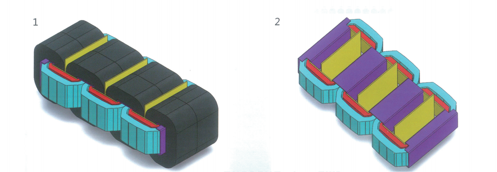
You must carefully match your equipment specifications to the grid's operational demands. We generally divide these units into two primary categories based on application and load behavior.
Power transformers serve as the backbone of transmission networks. They handle extreme voltages, often exceeding 33kV, and operate continuously near 100% load. Facilities use them as generator step-up units at power plants or step-down units at major utility substations. Their design prioritizes maximum continuous efficiency over varied load handling.
Distribution transformers perform a different role. They step down transmission voltages to safer levels for end-user commercial and industrial consumption. Manufacturers optimize them specifically for variable daily load cycles. A commercial facility might draw heavy power during business hours and minimal power at night. Distribution designs handle these fluctuations efficiently while minimizing standby energy losses.
Evaluating oil transformer types also requires analyzing physical deployment structures.
Pole-Mounted Units: These cylindrical tanks dominate residential and light commercial networks. They require zero ground space, making them ideal for dense urban routing.
Pad-Mounted Units: Housed inside secure, tamper-resistant green metal cabinets. Facilities deploy them for underground distribution lines in commercial parks, schools, and retail centers.
Substation Structures: These massive, fenced-in units serve heavy industrial applications. They feature exposed bushings, large radiator banks, and complex external monitoring panels.
Tank design fundamentally alters your future maintenance obligations. Conservator-tank models feature a secondary expansion tank mounted on top. As the internal fluid heats and expands, it flows into this conservator. Because the tank "breathes" outside air to accommodate volume changes, it uses a silica gel breather to strip moisture from incoming air. You must actively monitor and replace this silica gel.
Hermetically sealed units eliminate atmospheric contact completely. The corrugated steel tank fins expand and contract physically to absorb internal fluid pressure changes. These designs prevent moisture ingress and oxidation entirely. They offer a highly appealing "fit and forget" approach for modern distribution networks, drastically reducing routine maintenance labor.
When comparing liquid-filled units against dry-type cast resin alternatives, several operational realities become apparent. The exceptional thermal mass of an oil filled transformer provides a major advantage during peak demand. It handles temporary overloads far better than dry-type units. The massive volume of liquid absorbs sudden heat spikes without degrading the internal cellulose insulation.
Footprint and energy density also play a critical role in facility planning. Liquid-filled units achieve significantly higher kVA ratings within a comparatively smaller physical space. Air-cooled units require extensive internal spacing between coils to dissipate heat. Liquid insulation allows coils to sit much closer together. This compact energy density frees up valuable real estate at your facility for other operational needs.
Acoustic profiles present another distinct oil immersed transformer benefits. All magnetic cores exhibit magnetostriction—a physical expansion and contraction of core steel that generates a continuous hum. The heavy liquid inside the tank acts as a natural sound dampener. You will notice significantly lower noise levels compared to the louder, echoing hum of air-cooled alternatives. This matters greatly for installations near office buildings or residential zones.
Finally, we must consider equipment longevity. These units boast an expected lifespan of 30 to 40 years. This durability relies heavily on preserving the solid cellulose paper insulation. Because the liquid prevents oxygen and moisture from aggressively attacking this paper, the unit operates reliably for decades. However, achieving this maximum lifespan requires strict adherence to scheduled testing routines.
High-voltage assets introduce inherent physical risks. You must prioritize safety protocols and regulatory compliance from the initial design phase. Deploying an oil immersed transformer requires careful site preparation.
Outdoor installations demand strict spatial clearances. Industry standards dictate minimum distances between the equipment and adjacent buildings. You often need to construct concrete blast walls or physical firewalls between adjacent units. These barriers prevent a catastrophic failure in one unit from cascading into a multi-unit fire.
Indoor use introduces extreme regulatory hurdles. You must comply with National Electrical Code (NEC) or IEC indoor vault requirements. Standard mineral oil setups require heavily reinforced, fire-rated concrete vaults with specialized ventilation and automatic suppression systems. Upgrading to less-flammable K-class ester fluids often helps facilities satisfy these strict indoor mandates with less structural expense.
Environmental containment remains completely non-negotiable. Federal and local regulations usually require comprehensive Spill Prevention, Control, and Countermeasure (SPCC) plans. You must construct secondary containment systems, such as concrete catch basins or earthen moats beneath the unit. These basins must typically hold 110% of the unit's total fluid volume. This prevents catastrophic soil and groundwater contamination if a tank ruptures or a valve fails.
Reliability relies heavily on proactive condition monitoring. You cannot simply install the unit and ignore it. Mandatory Dissolved Gas Analysis (DGA) serves as your primary diagnostic tool. As internal faults develop, they generate specific trace gases (like hydrogen, methane, or ethylene) that dissolve into the fluid. Annual DGA testing detects these incipient faults—such as partial discharge or slight arcing—long before they cause a complete unplanned outage.
Best Practice: Establish a baseline DGA signature immediately after installation. Compare all subsequent annual tests against this baseline to track the rate of gas generation accurately.
Specifying equipment requires a highly methodical approach. Purchasing based solely on the lowest initial capital cost frequently results in poor long-term efficiency. You must evaluate specific oil transformer applications using a standardized checklist.
Establish your baseline technical requirements first. Provide vendors with exact specifications for your grid connection. You need to define the exact primary and secondary voltage ratio. Specify the required vector group (e.g., Dyn11) to ensure proper phase synchronization. Detail the desired impedance voltage to manage short-circuit currents, and finalize the continuous kVA capacity rating.
Next, perform a rigorous efficiency evaluation. Instruct your buyers to calculate the capitalization of energy losses over a projected 20-year horizon. You must analyze two specific metrics:
No-load (Iron) Losses: Energy consumed by the magnetic core simply by being energized. This loss remains constant 24/7, regardless of facility power usage.
Load (Copper) Losses: Energy lost as heat through the internal windings. This loss varies quadratically based on your facility's actual power draw.
By monetizing these guaranteed loss values, you can accurately compare actual vendor energy performance rather than just looking at the initial purchase price.
Table 1: Key Procurement Evaluation Metrics
| Evaluation Category | Critical Parameters | Primary Purpose |
|---|---|---|
| Baseline Specifications | kVA Capacity, Voltage Ratio, Impedance | Ensures exact electrical matching with the local grid. |
| Efficiency Metrics | No-load (Iron) & Load (Copper) Losses | Measures long-term energy performance and operational sustainability. |
| FAT Verification | Temperature Rise Limits, Dielectric Tests | Validates structural integrity and guaranteed electrical performance. |
Vendor auditing guarantees equipment quality. Demand comprehensive Factory Acceptance Testing (FAT) data before shipment. You or an independent inspector should ideally witness these tests. Critical FAT protocols include dielectric withstand testing, temperature rise limits under load, and lightning impulse voltage testing. These standardized IEEE/IEC tests verify that the unit meets all design promises before it ever leaves the manufacturing floor.
Finally, plan your delivery logistics carefully. Handling heavy, liquid-filled assets requires specialized rigging and transport permits. Larger units often ship drained of fluid and filled with dry nitrogen to reduce weight. You must coordinate specialized contractors to pull a vacuum and perform final oil-filling on site. Ensure your chosen manufacturer provides robust warranties, detailed installation manuals, and responsive commissioning support.
An oil-immersed unit remains the definitive industry standard for high-voltage, high-capacity infrastructure. It delivers unmatched thermal management, superior dielectric efficiency, and exceptional overload resilience. While dry-type units serve niche indoor applications, liquid-filled designs continue to power the vast majority of global transmission and distribution networks.
Decision-makers must prioritize long-term operational performance over the lowest initial bid. Demand vendor transparency, require validated Factory Acceptance Testing, and strictly evaluate energy loss metrics during the procurement phase. By planning for comprehensive environmental containment and rigorous condition monitoring, you ensure your infrastructure operates reliably for decades.
To finalize your procurement strategy, follow these critical next steps:
Document your exact load requirements, impedance needs, and vector groups before soliciting manufacturer bids.
Design secondary containment basins and fire suppression systems early in your facility planning phase.
Demand comprehensive FAT documentation, prioritizing temperature rise and dielectric impulse testing.
Establish a strict annual maintenance schedule focused on Dissolved Gas Analysis (DGA) and dielectric moisture testing.
A: These units typically last 30 to 40 years under normal operating conditions. However, this lifespan depends heavily on your load management and internal fluid purity. Consistent overloads degrade the internal cellulose paper. Regular fluid testing and moisture removal are critical to maximizing the equipment's operational life.
A: Yes, but indoor installations face strict regulatory barriers. The National Electrical Code (NEC) and IEC standards require highly specialized, fire-rated concrete vaults for standard mineral oil units. Using less-flammable K-class ester fluids can significantly reduce these structural requirements and simplify indoor deployments.
A: You should test the fluid at least once a year. Annual Dissolved Gas Analysis (DGA) and dielectric strength testing serve as the baseline for preventive maintenance. These tests detect incipient faults, moisture ingress, and paper degradation long before the equipment experiences a catastrophic failure.
A: The primary difference lies in the cooling medium. Liquid-filled units use oil to manage heat and insulate components, offering higher capacities and better overload tolerance. Dry-type units rely on ambient air cooling and cast resin insulation. Dry-types are safer for indoor use but lack the high-voltage capacity and compact footprint of liquid-filled designs.


