


Views: 0 Author: Site Editor Publish Time: 2026-09-01 Origin: Site


Selecting the wrong transformer quickly leads to spatial inefficiencies, code compliance failures, or premature equipment burnout. Modern commercial and industrial facilities rely heavily on stable electrical infrastructure. Without a clear understanding of the core categories, facility managers and electrical engineers risk specifying equipment ill-suited for their load profile. This oversight dictates heavy capital expenditure, inflates ongoing maintenance budgets, and compromises overall facility safety.
You need a reliable framework to navigate these complex electrical decisions. In this guide, we cut through the dense technical noise to provide a straightforward breakdown of the primary equipment categories you will encounter. You will learn how to evaluate different cooling configurations, assess crucial performance metrics, and apply accurate specification logic. By the end, you will know exactly how to match your facility's unique operational demands to the correct hardware.
Application dictates function: The four fundamental types of transformers used in commercial and industrial settings are Power, Distribution, Isolation, and Instrument transformers.
Cooling impacts footprint: Choosing between a dry type transformer and an oil immersed transformer hinges on indoor vs. outdoor placement, fire safety regulations, and maintenance bandwidth.
Compliance is non-negotiable: Procurement must align with specific NEMA/IEEE standards, local fire codes, and load scalability requirements.
Total Cost of Ownership (TCO): Upfront unit cost is secondary to operational efficiency, lifespan, and maintenance requirements.
Approaching an electrical hardware purchase requires a strong business lens. Engineers generally divide transformer classification into two distinct categories. The first category evaluates the application. This defines what the unit actually does within your electrical circuit. The second category evaluates the cooling medium. This defines how the unit prevents internal overheating during operation.
Understanding your system architecture helps narrow your choices. You must map exactly where this equipment sits in your facility's power hierarchy. Electricity travels from high-voltage grid transmission networks down to local substations. From there, it enters your facility and steps down further to power sensitive equipment. Every tier in this hierarchy demands a specific hardware profile.
While dozens of niche configurations exist in the market, establishing a baseline keeps your procurement process focused. Commercial and industrial facilities primarily evaluate four distinct functional categories. You do not need to master every obscure electrical variant. You simply need to understand these four core functions to make safe, efficient purchasing decisions.
Identifying the correct types of transformers begins with mapping your exact operational requirements. Below, we explore the four main functional categories you will encounter.
Table 1: Quick Comparison of Transformer Functions
| Functional Type | Primary Role | Typical Application | Key Success Metric |
|---|---|---|---|
| Power | High-voltage step-up or step-down | Utility grid to substation bridging | Maximum efficiency at 100% continuous load |
| Distribution | Step down to commercial voltage levels | Facility power delivery (480V/208V/120V) | High efficiency at fluctuating 50-70% loads |
| Isolation | Decouples sensitive equipment (1:1 ratio) | Data centers, medical imaging, CNC machines | Complete galvanic isolation and noise reduction |
| Instrument | Step down current/voltage for metering | Protective relays, billing, SCADA systems | High accuracy class for fault response |
The power transformer handles heavy-duty, high-voltage bridging. It acts as the critical link between the utility grid and your local substations. These robust units either step up voltage for long-distance transmission or step it down for regional distribution.
Success relies on continuous maximum load operation. Engineers design these units to achieve peak efficiency when operating near 100% capacity. They do not handle load fluctuations well. Instead, they thrive in environments demanding steady, unyielding power delivery over long durations.
The implementation reality involves heavy logistical planning. You must account for a massive physical footprint. Installation requires extensive site preparation, including reinforced concrete pads. Strict environmental containment regulations also apply, ensuring site safety against potential fluid leaks.
Best Practice: Always consult IEEE C57 standards when defining thermal limits for these units.
Common Mistake: Underestimating the site preparation timeline. Approvals for concrete pouring and fluid containment berms often delay commissioning.
A distribution transformer steps down voltage from the regional grid to usable levels. This brings high voltage down to standard commercial usages, such as 480V, 208V, or 120V. Most commercial facilities interact directly with this category.
Unlike units on the transmission grid, these devices excel at fluctuating loads. They rarely operate at full capacity. Success criteria demand high efficiency when running at 50% to 70% of their total rating. This load profile matches the daily operational shifts of typical industrial plants and office buildings.
This category represents the most common facility purchase. Sizing accuracy plays a pivotal role here. Proper sizing prevents long-term energy waste known as core losses. Over-sizing wastes capital, while under-sizing causes dangerous overheating.
Best Practice: Analyze your facility's daily peak demand curve to pinpoint the optimal 50-70% efficiency sweet spot.
Common Mistake: Neglecting Department of Energy (DOE) efficiency requirements during the specification phase.
An isolation unit decouples highly sensitive equipment from the main power source. It typically utilizes a 1:1 voltage ratio. This means it does not step the voltage up or down. Instead, it provides a protective electrical barrier.
The primary success criteria involve complete galvanic isolation. This process separates the input circuit from the output circuit physically. Doing so eliminates electrical noise, suppresses harmful harmonics, and prevents destructive ground loops.
The implementation reality makes this category critical for high-stakes environments. Medical facilities rely on them for precise MRI and X-ray imaging. Data centers use them to protect servers from grid spikes. Precision CNC manufacturing lines require them to maintain strict tooling tolerances.
Instrument units safely step down high currents or high voltages. They include Current Transformers (CTs) and Potential Transformers (PTs). They reduce dangerous power levels to safe, measurable increments for metering equipment and protective relays.
Success depends entirely on their accuracy class. Utilities and facility managers rely on these devices for exact billing calculations. Furthermore, protective relays depend on this accuracy for immediate fault response. If a spike occurs, these units signal the breakers to trip instantly.
The implementation reality shows a much smaller physical footprint. Despite their small size, they remain absolutely critical. You cannot achieve facility safety compliance or accurate power quality monitoring without them.
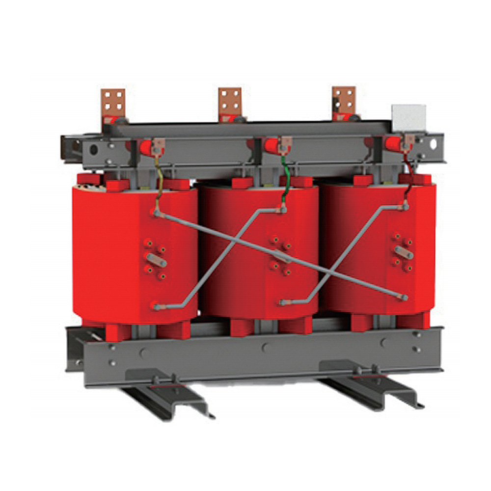
Selecting a cooling medium represents the primary decision point for buyers. Facility managers must choose the right system when specifying indoor or distribution hardware. This choice directly impacts facility safety, ongoing maintenance, and physical space allocation.
A dry type transformer cools its internal coils using ambient air flow. They often utilize Cast Resin or Vacuum Pressure Impregnated (VPI) technologies to protect internal windings.
These units are best for indoor installations. You will commonly see them in commercial office buildings, schools, hospitals, and environmentally sensitive areas. They thrive where fluid leaks present unacceptable risks.
The pros center around safety and simplicity. They present zero fire risk because they contain no flammable liquids. You do not need to build expensive spill containment berms. Furthermore, they demand very low ongoing maintenance compared to their liquid-filled counterparts.
However, you must consider the trade-offs. They require a significantly larger physical size to achieve the same kVA rating as liquid units. They also carry a higher upfront cost. Finally, they remain highly susceptible to harsh, dusty environments unless you enclose them strictly in NEMA 3R or NEMA 4 rated housings.
An oil immersed transformer submerges its internal windings in a dielectric fluid. This fluid, usually mineral oil or synthetic ester, acts as both an insulator and a highly effective cooling medium.
These devices are best for outdoor substations. Heavy industrial plants and high-capacity transmission networks rely on them heavily. They perform exceptionally well in harsh outdoor environments.
The pros include a much smaller physical footprint for high power ratings. The fluid provides highly efficient cooling. This allows the unit to handle temporary overloads much better than air-cooled designs. They also generally offer a lower upfront purchase cost.
The risks involve strict environmental compliance. You must install robust spill containment berms to prevent soil contamination. They require regular fluid testing, known as Dissolved Gas Analysis (DGA), to monitor internal degradation. Finally, you must strictly adhere to fire separation codes regarding proximity to occupied buildings.
Specifying different transformer types requires a multifaceted evaluation. You cannot rely on a single metric. Facility leaders must balance spatial constraints against energy requirements and supply chain realities.
First, evaluate load sizing and scalability. You must avoid the trap of over-sizing your equipment. Excessive capacity leads to continuous energy waste and higher initial costs. Conversely, under-sizing causes frequent overheating and operational bottlenecks. A common engineering best practice factors in a 20-25% buffer to accommodate future facility expansion.
Second, prioritize efficiency and compliance. Always verify your selected equipment aligns with current Department of Energy (DOE) efficiency standards. Review the manufacturer's testing data to ensure compliance with IEEE and ANSI testing protocols. Missing these certifications can result in failed building inspections.
Third, assess your spatial and structural realities. Liquid-filled units weigh significantly more than air-cooled units. You must verify your facility's floor loading capacities before installation. Measure all doorway clearances carefully to ensure safe rigging and transportation. For air-cooled units, calculate the room's ventilation requirements to prevent ambient overheating.
Finally, acknowledge current lead times. The electrical hardware supply chain faces ongoing constraints. Custom configurations often require 30 to 50 week lead times. If your project runs on a tight schedule, you should pivot toward standard, off-the-shelf configurations to prevent delays.
Even perfectly specified equipment can fail if installed incorrectly. You must proactively manage implementation risks. Poor grounding remains a top installation pitfall. Without proper grounding, electrical noise spikes and endangers connected machinery. Inadequate harmonic mitigation represents another major risk. If you power non-linear loads like variable frequency drives (VFDs) or heavy IT servers, you must specify appropriate K-factor ratings. Ignoring extreme ambient temperatures in the installation space also leads to rapid insulation degradation.
To avoid these pitfalls, follow a structured shortlisting logic:
Define the exact application requirement (e.g., Power, Distribution, or Isolation).
Audit the installation environment to decide between Indoor and Outdoor placement (guiding your Dry vs. Oil decision).
Calculate both your continuous load and your peak load requirements accurately.
Your next step requires professional collaboration. Do not finalize specifications in a vacuum. Consult with a specialized electrical engineering firm. Alternatively, engage directly with a knowledgeable manufacturer representative. Provide them with your facility's single-line diagram and your complete load profile. This collaboration ensures you receive a highly accurate, risk-free spec sheet.
Understanding the fundamental categories of electrical hardware acts as your first line of defense in protecting facility infrastructure. You cannot treat these purchases as simple commodity acquisitions. The reliability of your entire operation depends on matching the right hardware to the right task.
Your procurement strategy should always be driven by specific application demands and environmental constraints. Resist the urge to purchase based solely on immediate availability or the lowest initial sticker price. Evaluate operational efficiency, expected lifespan, and long-term maintenance requirements.
Take action today by auditing your current electrical infrastructure. Evaluate your immediate facility needs against your projected five-year expansion plans. Only after you define this complete operational picture should you begin requesting formal quotes from manufacturers.
A: Power transformers operate near full load for transmission networks, moving high-voltage electricity over long distances. Distribution transformers step down that voltage for commercial end-use. Engineers optimize distribution units to run efficiently at fluctuating, lower-capacity loads typical of daily facility operations.
A: Choose dry-type designs for indoor, commercial, or environmentally sensitive locations. They eliminate fire risks associated with flammable fluids. They also bypass the need for expensive oil spill containment berms, making them ideal for high-traffic or heavily regulated indoor spaces.
A: Base your classification on three main factors. First, identify the required voltage step (application). Second, assess the installation environment (cooling method). Finally, evaluate the sensitivity of your connected equipment, such as determining if medical or CNC devices require strict galvanic isolation.
A: A K-factor rating indicates a dry-type unit's ability to withstand the heating effects of non-linear loads without failing. Non-linear loads, generated by computers, LED lighting, or variable frequency drives (VFDs), create harmonic distortion. Higher K-factor ratings handle higher levels of these damaging harmonics safely.


